NVDB Feature panel - Editing features
Create a new NVDB feature
To create a new NVDB feature follow these steps:
- Select an NVDB layer in the Feature panel layer selector. The type of NVDB objects of the layer selected will determine the type of objects that can be created with the creation buttons. If a creation button is disabled that means that the NVDB object type of the layer do not allow that type of geometry. One NVDB object can have several geometries of different types. The creation buttons, located in the button bar of the Features section, are these:
- Create new point feature
 to create a new object with its main geometry as a point.
 - Create new polyline feature
 to create a new object with its main geometry as a polyline.
 - Create new polyline feature
 to create a new object with its main geometry as a polygon.
- Create new point feature
- Click in the viewer to position vertex for the new feature. Points features only require one click, while polylines or polygon features require several points and a double-click (double tap) in final point.
- The new feature is created and stored in Mapspace temporary storage services. The new created feature is marked with a white dot inside to signify that is a created object.
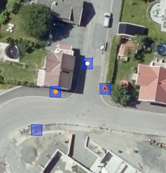
For example, in the snapshot below there are one new created NVDB feature (white dot), one modified NVDB feature (orange dot), one NVDB featured tagged for deletion (red dot) and finally one untouched NVDB feature (without dot). This dots are shown only in 2D viewers, not in 3D viewers.
A new created feature is automatically populated with default values for all attributes that are defined as PÅKREVD_ABSOLUTT (required) or PÅKREVD_IKKE_ABSOLUTT (required but not absolutely) in NVDB catalog.
Depending on the type of geometry created, the feature is populated with a geometry attribute of the type of geometry selected. The geometry attribute used is the first founded in the object type definition that is of the same type as the geometry. Also, a Geometry attribute property is populated in the created feature with the ID of the geometry attribute used. This geometry attribute is added to the newly created feature no matter if the attribute is defined as PÅKREVD_ABSOLUTT (required) or PÅKREVD_IKKE_ABSOLUTT (required but not absolutely). Even if the attribute is defined as OPSJONELL (optional) the geometry attribute is added. The WKT stored in the geometry attribute is a serialization as WKT of the geometry created, transformed to EPSG:25833 projection.
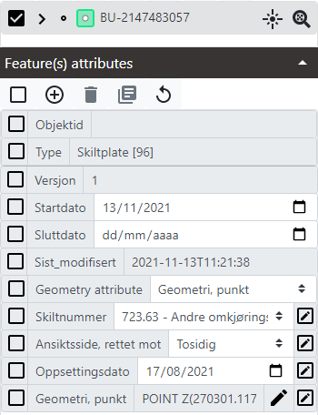
In the example below we have created a point feature. As it is a new created feature, there is no value in the Objektid property. This is an internal value that will be set when the feature is sent to NVDB Write services. The Geometry attribute is set by default to the unique geometry attribute that is available for this case of object (that is an Skiltplate). Under it we see four attributes added with values by default, including the Geometry, punkt attribute that is filled with the appropiate WKT and metadata values.
Elevation of newly created features
Elevation for new created features is set in different ways depending on the type of viewer:
- For 2D viewers, elevation is only added if in the Snapping options the option Auto-snap Z to terrain requesting Z from Field Group services is set to true. Check below the Setting snapping options section for more on how to set this option. When the option is set, elevation is requested to Field Group services and applied to the new created geometry. For polylines and polygons all the vertex are set with the elevation of the first vertex.
- For Street viewers, elevation is set by default at ground level in the location of the camera shot. Be aware that polylines and polygons, when set with the same elevation in all the vertex, is done in local coordinates, with axis oriented in the direction and rotations of the car that mounts the camera. Those coordinates, when converted to Mercator Spheric or any UTM projection, do not maintain the same elevation in each vertex. It is possible, anyway, to change the elevation of vertex using the Move vertex vertically tool. More on this tool later.
- For 3D viewers, elevation is set by default as an offset from the current terrain loaded in the viewer. This offset allows to draw polylines and polygons more easily on top of the terrain. It is possible, anyway, to change the elevation of vertex using the Move vertex vertically tool. Check Modify geometries - Move vertex vertically section.
Modifying geometries - Main & secondary geometries
Any NVDB feature can have several geometries associated. Geometries can be of two types:
- Main geometry. This is the geometry that is shown in viewers and can be edited using interactive tools on viewers. Coordinates can be in 2D or 3D for Map viewers and in 3D only for 3D viewers. The type of geometry of the main geometry will be the one that was used in the Creation buttons.
- Geometries in attributes. This are geometries that are serialized as WKT and stored in attributes. Each NVDB object type can contain one or several attributes with geometries. This geometries are not shown in viewers and only can be edited using the Edit NVDB geometry attribute dialog. One of these attributes can be defined as the one that corresponds to the main geometry using the Geometry attribute property that each feature has.
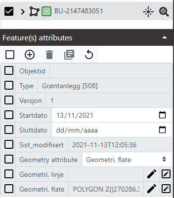
In the example below we have a feature of type Grøntanlegg with a pair of geometry attributes. One is the main geometry (Geometri, flate). It can be known because the Geometry attribute property is set as that attribute, and also the type of WKT (POLYGON Z) is the same shown as icon in feature list . Another attribute is called Geometri, linje, and this is not the main geometry but a simple attribute. Currently the attribute has no geometry defined in it and shows no WKT in it.
Modifying geometries - Move vertex horizontally
To modify a geometry of an existing NVDB feature or a newly created one moving any of its vertex in an horizontal plane follow these steps:
- Mark one or several feature in the Feature list. Only marked features will be affected by the Move vertex of marked features horizontally tool. This allows to easily move points that happens to be overlapped in the same point without accidentaly move an unwanted point.
- Click in the Move vertex of marked features horizontally tool in the button bar of the Features section.
 This button is an interactive tool.
 - Click in an NVDB feature vertex and drag it to move to a new location.
- If the feature is a polyline or polygon, click and drag in the middle of a segment to add a new vertex.
- If the feature is a polyline or polygon, Alt + click in a vertex to delete it. When a polyline has two vertex or a polygon has three vertex then no more vertex can be deleted.
When moving vertex it is possible to use snapping options to snap vertex to existing vertex in other layers. Check Setting snapping options section to know more about snapping options.
In 3D viewers, when moving vertex, Z values are always preserved (if they exist) so vertex are moved in a plane, either a local plane parallel to ground in Street viewers or a local ellipsoid parallel to main ellipsoid in 3D viewers.
In 2D viewers, when moving a vertex, Z values are updated or not depending on Snapping options. If the option Auto-snap Z to terrain requesting Z from Field Group services is set to true then each time a vertex is moved a new elevation is requested to Field Group services and elevation is updated. If the option is set to false then Z values are preserved.
Whenever a geometry is changed its geometry is saved in Mapspace storage services as long as changes are made. Also changes in the geometry are converted to WKT in EPSG:25833 projection and saved in the attribute that is defined in the Geometry attribute property, if any is defined.
Modifying geometries - Move vertex vertically
This tool is only available for 3D viewers.
To modify a geometry of an existing NVDB feature or a newly created one moving any of its vertex in a vertical plane follow these steps:
- Mark one or several feature in the Feature list. Only marked features will be affected by the Move vertex of marked features horizontally tool. This allows to easily move points that happens to be overlapped in the same point without accidentaly move an unwanted point.
- Click in the Move vertex of marked features vertically tool in the button bar of the Features section.
 This button is an interactive tool.
 - Click in an NVDB feature vertex and drag it vertically to move to a new Z location.
- Alt + click in a feature vertex moves that vertex vertically to ground, requesting elevation to Field Group services to know at what elevation is ground surface.
- Shift + click in a feature vertex moves that vertex vertically to ground, but using depthmap if it is available or the elevation at camera shot point for Street viewers, or using loaded terrain (if any) for 3D viewers.
This tool ignores Snapping options if they are activated.
Whenever a geometry is changed its geometry is saved in Mapspace storage services as long as changes are made. Also changes in the geometry are converted to WKT in EPSG:25833 projection and saved in the attribute that is defined in the Geometry attribute property, if any is defined.
Modifying geometries - Edit geometry attributes
To modify a geometry of an existing NVDB feature or a newly created one by editing the attributes, follow these steps:
-
Click in Edit geometry button
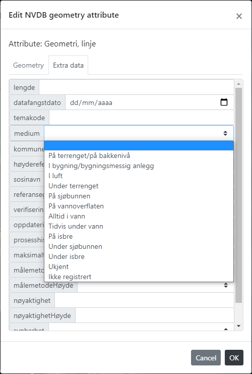
 on the right of any attribute that contains a geometry. The Edit NVDB geometry attribute dialog appears:
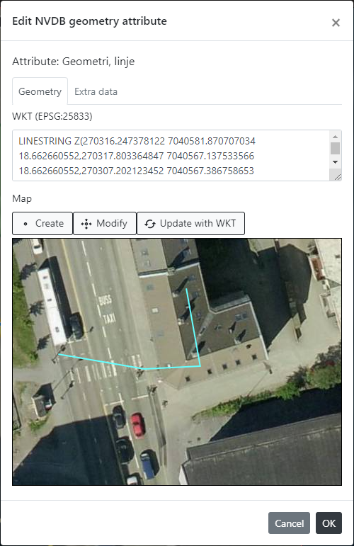
-
In the top of the dialog the name of the attribute is shown. Each attribute can be only of one type of geometries, and that determines the geometry that can be created in this dialog.
-
Next there are a pair of tabs: Geometry and Extra data. The first contains the controls to edit the geometry. The second contains controls to edit the metadata of the geometry following the allowed values for these metadata by NVDB.
-
In Geometry tab it is possible to create a new geometry or modify an existing one. For creating a new geometry, use any of these ways:
- Click the Create button to activate creation tool. Then click in the map in the dialog (one click for points or several for polylines and polygons with a double click at the end). When finished, the WKT is refreshed and the map shows the new created geometry. If an there was an existing geometry, then the new created one replaces previous.
- Type any valid WKT in the WKT textobox and then click in Update with WKT button. WKT must be of a valid type that matches the geometries that can be stored in current attribute edited, and coordinates must be in
EPSG:25833. If WKT is not valid, an error appears. If WKT is valid, the map is refreshed with new geometry.
-
For modifying an existing geometry, click in the Modify button to activate the modiying tool. Then click in the map in the dialog and drag in any vertex to move it. Click and drag in the middle of a segment to create a new vertex, or Alt + click in a vertex to delete it until limit of minimum vertex is reached. Each time a vertex is modified, the WKT textbox will be updated.
-
In this dialog is also possible to add extra data to the geometry or modify existing extra data. This extra data, when changed, implies a change in geometry even if the geometry WKT remain unchanged. For editing extra data select the Extra data tab.
-
To add an extra data type or select the appropiate value in the given fields.
-
To remove an extra data value just make the property empty removing any value.
-
To finish edition click OK button, or Cancel button to exit without doing any change.
-
If the attribute edited is the one defined as the main geometry, changes made to the WKT will be synced in the geometry itself.
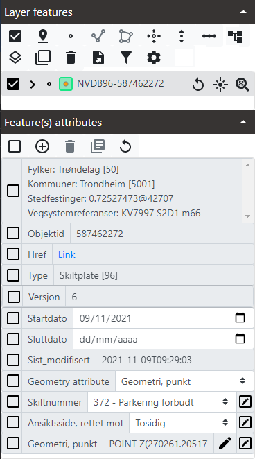
For example, the snapshot above shows one NVDB feature selected after edit a geometry attribute. Notice that the feature has one geometry attribute called Geometry, punkt. At the same time, this attribute is defined as the attribute with the main geometry, because the Geometry attribute property has defined this attribute as so.
Adding a linear reference to the NVDB road network
Each NVDB feature is linked to one or several road networks positions through a linear referencing system. The system allows to link to specific locations, to a range of locations, or to a node in the road network.
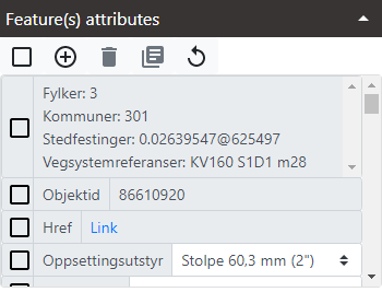
The existing linear referencing is shown in Attributes list as a Stedfestinger metadata. This value is a list of linear references. Each linear reference has this pattern: relative_number@road_subsection_ID. For example, 0.02639547@625497 means a location in the road subsection with ID = 625497 located at a length from origin that is about 2.64% of total length, so close to origin of the road subsection.
To add a linear reference to a feature follow these steps:
- Mark one or several features in the Feature list. The linear reference will be added to all marked features.
- Click in the Add or extend linear reference button.
 This is an interactive tool.
 - Click in the viewer in any location. The NVDB web services will be queried for an existing road near the location clicked. If a road is found, then the linear reference is extracted for the point clicked. It is not needed to click precisely on top of a road, or needed to have the NVDB road network drawn in the viewer at all.
- The new linear reference is added to existing ones and persisted in Mapspace temporary storage services.
Adding and removing related features to an NVDB feature
For adding a related feature to an existing one, follow these steps:
-
Ensure that the layer or layers with related features are added to current viewer, the layers are visible, and they are listed in the Feature panel layer selector.
-
Mark one or several features in the Feature list. Relationships will be added to all marked features.
-
Click in the Add a relationship button in the button bar of the Features section.
 This button is an interactive tool.
 -
Click in the viewer in any point. Any feature visible in that point that can be a related feature of the marked ones will be set as a child feature. The feature ID will be used to add the relationship. The relationship will be shown in Feature list treeview if the feature has related features expanded. The new added relationships are shown with an asterisk (*) on the right of the feature ID.
-
Any time a new relationship is added to an NVDB feature it is tagged as modified (orange dot) and changes are persisted inmediately in Mapspace temporary storage services.
For removing a relationship in any NVDB feature:
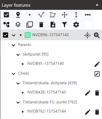
- Expand related features in any feature. Related features will be shown as childs in the Feature list treeview. Each related feature will show its ID and a Delete relationship button.
- Click in the Delete relationship button.

- The feature ID is shown as strikethrough if the feature is an existing NVDB feature and remove for newly created features. The change is inmediately persisted in Mapspace temporary storage services.
In snapshot below for the NVDB feature selected we have changed the relationship with objects of type ID = 762, and we have added one related object and removed an existing one.
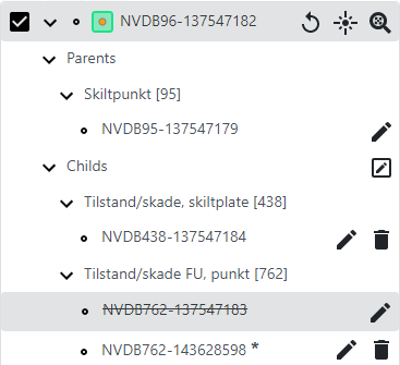
The Childs section has a Set as korriger button on the right. This button is a checkbox and when clicked it alternates between two states:
- As Oppdater:
 When in this state that means that any change made to the current list of childs will be sent to NVDB write services as an oppdater change. An oppdater change (or update) means that the change is a new state in the object and that the change must be saved in the historical versions of the object.
 - As Korriger:
 When in this state that means that any change made to the current list of childs will be sent to NVDB write services as a korriger change. A korriger change (or correction) means that the change is not needed to be saved in the historical versions of the object and is a fix of a previous bad state.
Click on the Set as korriger button in the Childs section of relationships when you want that any edits made to relationships in a feature are sent as Korriger changes instead as Oppdater.
Duplicating NVDB features
To duplicate one or several NVDB features, follow these steps:
- Mark one or several features in the Feature list.
- Click in the Duplicate features button in the button bar of the Features section.

- Marked features are duplicated, with temporary Mapspace ID instead of original NVDB ID, but maintaing all attributes and related features, and saved in Mapspace temporary storage services.
- Duplicated features are the same as newly created features and are shown with a white dot inside.
Deleting NVDB features
To delete one or several NVDB features, follow these steps:
-
Mark one or several features in the Feature list.
-
Click in the Delete features button in the button bar of the Features section.
A Confirm removal of NVDB object dialog appears.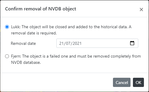
-
The dialog lets select one option, either Lukk or Fjern as removal mode. Lukk means that the NVDB object will be closed and current version will be added to historical data. This case requires to select a removal date. Fjern means that the object is a bad one that shouldn't exist in NVDB database and completely remove it without saving any historical data.
-
The options in the dialog are only applied to existing NVDB objects, not newly created ones. For them this option is ignored.
-
Click OK button in dialog to proceed or Cancel button to exit deletion process. If OK deletion process will start.
-
The result depends on the type of marked feature:
- for newly created features: this features are removed from viewers and from Mapspace temporary storage services. This deletion is permanent and cannot be undone.
- for existing NVDB features, they are tagged for deletion and saved as so in the Mapspace temporary storage services.
-
Existing NVDB features tagged for deletion are shown with a red dot inside.
Reseting changes in any NVDB feature modified
To reset changes to an existing NVDB feature:
- Mark one feature in the Feature list.
- Click in the Reset button in the row of the feature.
 This button only appears for modified existing NVDB features or features tagged for deletion.
 - Changes are removed from Mapspace temporary storage services. For modified features, NVDB features are restored. For features tagged for deletion, the deletion tag is removed.
Setting snapping options
Snapping options are set for each layer and are persisted in the workspace when it is saved.
To setup snapping options follow these steps:
-
Select one NVDB layer in the Layer selector of the Feature panel.
-
Click in the Snapping options button.

-
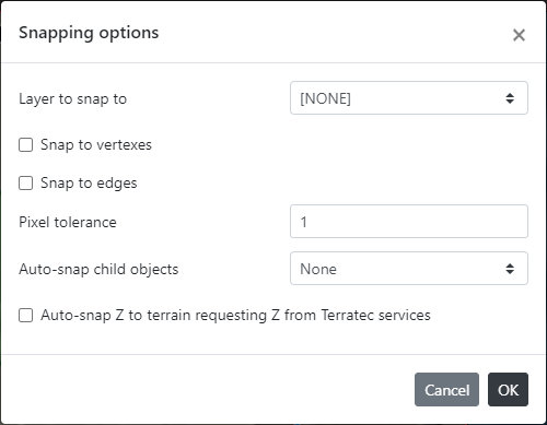
The Snapping options dialog opens.
-
Select an existing vector layer or select NONE to deactive snapping options. The layer to snap to can also be the current selected layer in the Feature panel layer selector to snap to itself.
-
Check if snap to vertex or not in the Snap to vertexes checkbox.
-
Check if snap to edges (lines but not vertex of lines) in the Snap to edges checkbox.
-
Select a pixel tolerance, the number of pixels at which vertex snap by proximity.
-
Select if auto-snap child objects when the feature has related child objects. This option only works for features that are points. The options are:
- None: changes in geometry are not applied to child objects.
- Parent absolute location: child objects are moved to new location of parent.
- Parent relative location: child objects are moved the relative distance between old and new location of parent.
-
Check the Auto-snap Z to terrain requesting Z from Field Group services checkbox if you want to automatically set elevation values to vertex in geometries when they are created or modified. This option do not requires to have any layer selected in the dialog.
-
Click OK button to accept.
Snapping options are persisted in the workspace (for super users) as properties of the layers. Each selected layer in the Feature panel can have one layer to snap to with the options of the dialog. The layer to snap is persisted as a layer name, so be aware that if the name of the layer changes or the layer is removed, then the snapping will not take effect.
Other useful information of NVDB functionality: